


Explore Our Services and Solutions
Delivering Value to Our Ecosystem

Procure Ease
Bridging Businesses and the Best Raw Material Sources with Perfect Industrial Procurement Solutions Stronger Together with features Group Buying

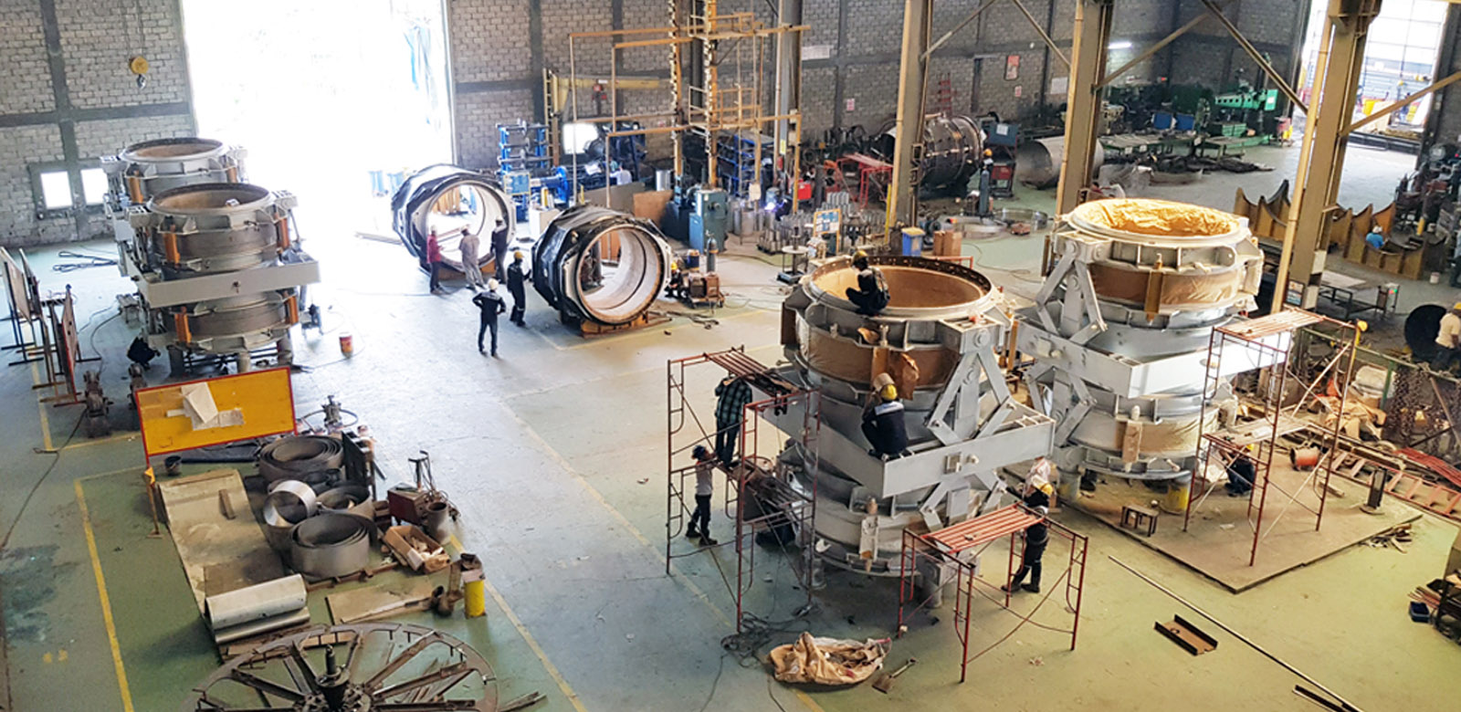
E-Cloud Manufacturing
Pioneering the Future of Manufacturing: Discover higher levels of process efficiency and agility with our manufacturing services, shaping the future of the production industry.

Global Trade
Seizing Global Opportunities with Local Expertise: Optimizing Trade for Your Business Success

Credit Flow
Pioneering Growth Opportunities, Securing Supply, Unlocking Business Potential through Smart Supply Chain Financing
Explore Categories
Explore a Wide Range of Standard Industrial Products and Fabrication


Our Comprehensive Solutions for Your Business Growth

Procure Ease
Bridging Businesses and the Best Raw Material Sources with Perfect Industrial Procurement Solutions
Stronger Together with
features Group Buying
Stronger Together with
features Group Buying

E-Cloud Manufacturing
Pioneering the Future of Manufacturing:
Discover higher levels of process efficiency and agility with our manufacturing services, shaping the future of the production industry.
Discover higher levels of process efficiency and agility with our manufacturing services, shaping the future of the production industry.

Global Trade
Seizing Global Opportunities with Local Expertise:
Optimizing Trade for Your Business Success
Optimizing Trade for Your Business Success

Credit Flow
Pioneering Growth Opportunities, Securing Supply:
Unlocking Business Potential through Smart Supply Chain Financing
Unlocking Business Potential through Smart Supply Chain Financing
Free Online Consultation with Product Specialists
Resolve Your Challenges with a Free Online Consultation Now
Partnership
Stay Connected with All Your Friends
Exciting Programs from Fajar Benua Industries to Provide Daily Benefits for You.
Register as a Vendor
Inviting suppliers of goods/services to become registered partners at Fajar Benua Industries
Affiliate Program
Earn passive income from affiliates by
referencing products and services from Fajar Benua Industries.
referencing products and services from Fajar Benua Industries.
Collaboration
We welcome various collaborations such as community partners, media partners, product vendors, and more.
Why Fajar Benua Industries

Online Offers
Request Documents are available online and can be easily printed

Sales Assistant
Our Sales Team is always ready to assist you for a comfortable shopping experience
TOP Program
Shopping solutions with term payments tailored to your preferences
Payment Methods
There are various convenient payment method options available.