Thermal Stress Analysis of Frame Fabric Expansion Joints
Abstract
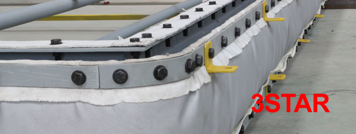
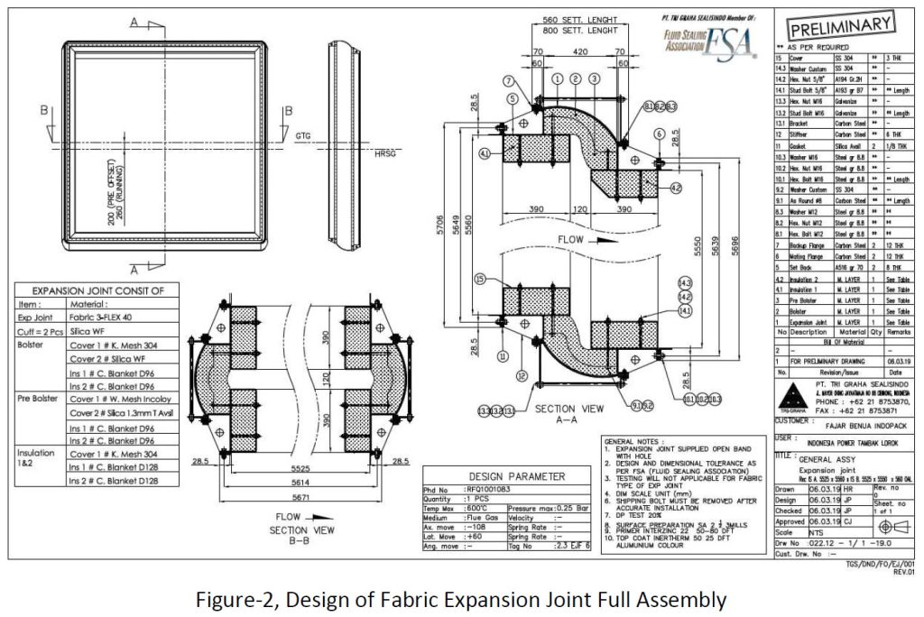
The frame expansion joint is a ducting connection construction where the Fabric Expansion joint is installed in the frame, whether it is installed in the Power Plant or other Plants.
Performance The frame must be designed according to the standard so that the frame can operate properly without cracking at the weld joint at the specified working temperature. Failure of the frame expansion joint will result in the failure of the fabric expansion joint and losses due to down time in a plant.
To ensure the frame’s resistance to temperature changes, simulations with FEA are needed. there is a linear relationship between the change in temp and the resulting voltage
The analysis was carried out by simulating the model with internal thermal loading in the form of conduction of 600°C on the inner side of the frame and free air convection on the outer side of the frame. The thermal conductivity value of Carbon Steel material is 45 W/m2.K, while Stainless Steel is 15 W/m2.K, Thermal Expansion Carbon Steel is 10.8 x 10⁻⁶ /°C, while Stainless Steel is 16.9 x 10⁻⁶/°C
This study will explain how the frame reacts when the frame works at a working temperature of 650 C where the frame consists of 2 different materials:
- Frame Carbon Steel A516 Gr. 70 ;
- Scallop Stainless Steel 304
Introduction
In mechanics and thermodynamics, thermal stress is a mechanical stress created by any change in the temperature of a material. These stresses can cause fracture or plastic deformation depending on other heating variables, including material type and limitations. Temperature gradients, thermal expansion or contraction and thermal shock are things that can cause thermal stress. This type of stress is highly dependent on the coefficient of thermal expansion which varies from material to material. In general, the greater the change in temperature, the higher the level of stress that can occur. Thermal shock may result from rapid changes in temperature, resulting in cracking or breaking.
The application of the Frame Expansion joint is as a connector of the ducting as the exhaust path for combustion gas boilers or gas turbines. In the combustion process there is a thermal loading caused by the combustion of gas in the boiler or gas turbine. Furthermore, thermal loading will cause an expansion effect on both carbon steel and stainless steel materials. because there is a difference in the value of different thermal expansion, then the amount of expansion will be different. It is very important to analyze the effects of these expansions, but because manual calculations have many limitations.
Software based on the finite element method can be used as a solution to overcome these problems.
The purpose of this research is to analyze the maximum allowable stress and to analyze the thermal effects that occur in the frame.
Research Methodology
In this study, thermal and stress analysis will be carried out on the results of the Frame Expansion Joint design. Thermal analysis is carried out in the form of stresses that occur due to differences in temperature distribution in a material where the amount is equivalent to the strain that arises in an expanding material which is also called thermal stress.
Then, a stress analysis will be carried out on these components which aims to find the location and magnitude of the maximum applied stress using software based on the finite element
method.
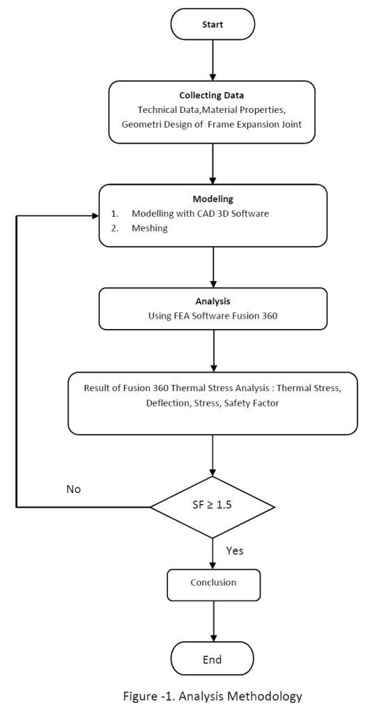
Furthermore, the steps that the researcher will take to fulfill the research objectives and solve
the problem formulation above are shown in Figure 1 below:
Methode & Solusion
3.1 Modelling
In this research, modeling is done using Fusio360 software. Before analyzing the designed thermal frame expansion joint, the simulation model used needs to be validated. Validation is done by comparing the simulation results with analytical calculations.
3.1.1 Finite Element Calculation
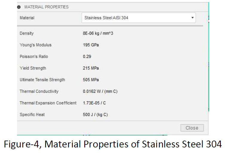
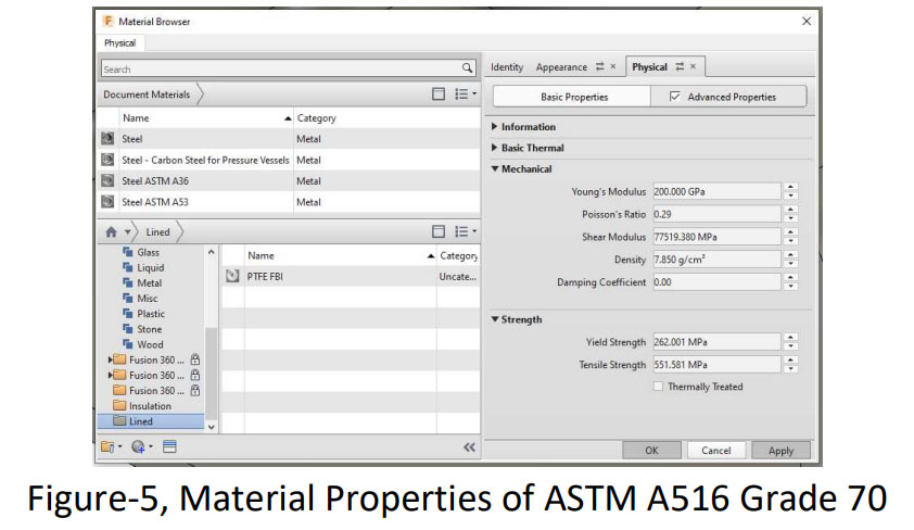
The first step in validation is to perform a simulation with half of the existing model. In this simulation, the left side frame consists of a combination of 2 different materials. Frame with material A516 Gr. 70 and Scallop with 304 Stainless Steel material.
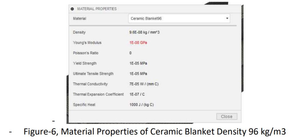
The data on the mechanical properties of these components are as follows :
Scallop Stainless Steel 304
Frame material ASTM A516 Gr. 70
Insulation Ceramic Blanket Density 96 kg/m3
3.2 Manual Calculation
Analytical calculations are carried out with the following thermal stress formula:
Ɛ =αΔT……(1) :
Ɛ = Strain
α = Thermal expansion coefficient
ΔT = temperature difference
E = ϑ/Ɛ…….(2) :
E = Young Modulus
ϑ = Stress
Ɛ = Strain
ϑ = EαΔT…….(3)
ϑ = Stress
E = Young Modulus
ΔT = temperature difference
3.3 Simulasi Frame Expansion Joint
Simulation of loading on the frame is carried out by applying thermal loads both internally and externally.
The simulation is divided into 4 parts as follows:
3.3.1 Full Assembly Thermal Simulation
3.3.2 Scallop Thermal Stress Simulation
3.3.3 Insulation Thermal Stress Simulation
3.3.4 Frame Thermal Stress Simulation
3.3.1 Full Assembly Thermal Simulation
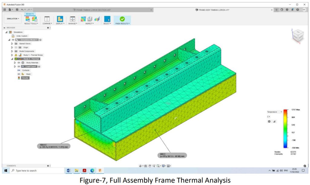
In this simulation, the author wants to know the temperature distribution on the component parts of Scallop, Insulation and Frame.
According to the results of the thermal simulation, the temperature data achieved on the surface of the frame in contact with the insulation is 108.6 °C
3.3.2 Scallop Thermal Stress Simulation
Thermal Calculations In this calculation, the thermal load is applied to the wall surface of the Scallof which is in direct contact with the heat by 600 °C, while in the area that is not in direct contact with the heat, a radiation load of 300 °C is given with emissivity = 1.
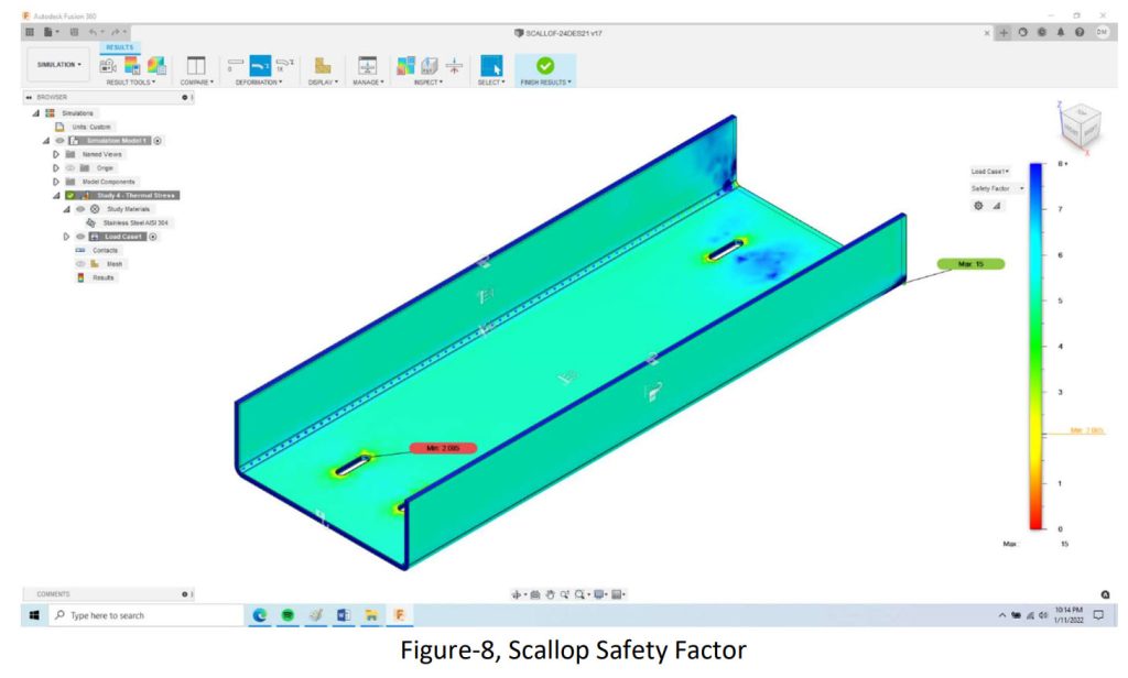
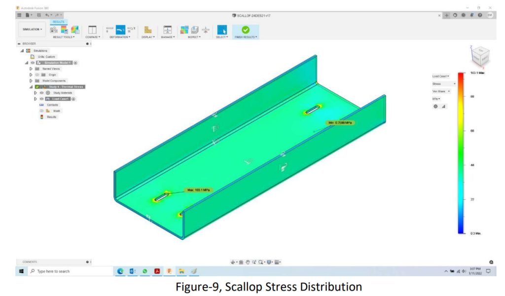
Finite Element simulation results show the maximum stress that occurs is 89.91 MPa. This value is still far below the Yield Strength of SS304, which is 215 Mpa. The safety factor achieved from the simulation results is 2,391. The maximum stress that occurs is 103.1 Mpa
3.3.3 Insulation Thermal Stress Simulation
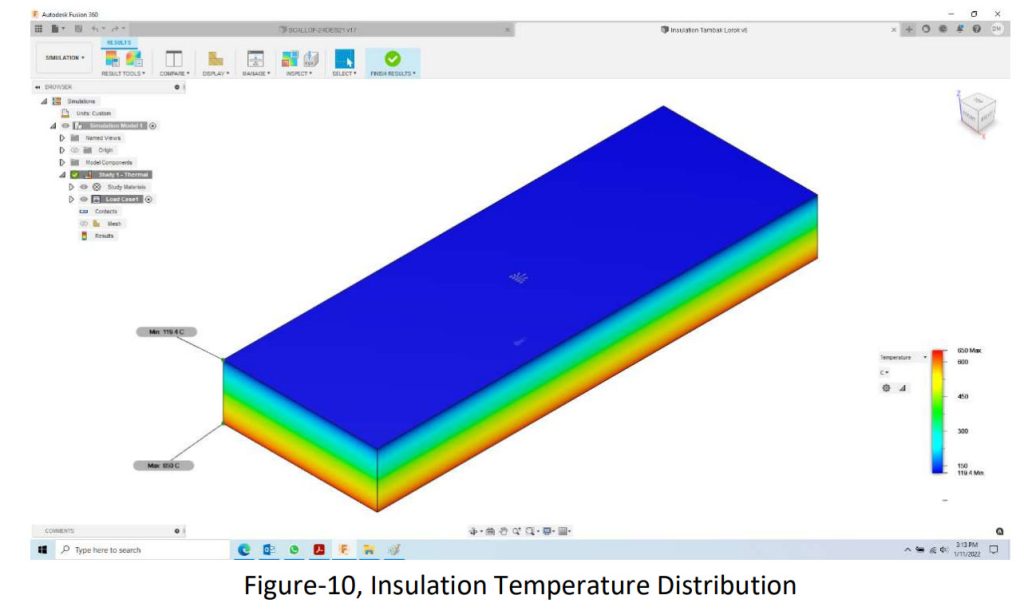
The material used for insulation is Ceramic Blanket with a specific gravity of 96 kg/m3, with a continuous temperature resistance capability of 1000 °C. Thermal insulation loading is done by applying a temperature of 600 C to the part that is in direct contact with the Scallof surface, the simulation results show that the insulation surface temperature in contact with the frame surface is 119 °C.
3.3.4 Frame Thermal Stress Simulation
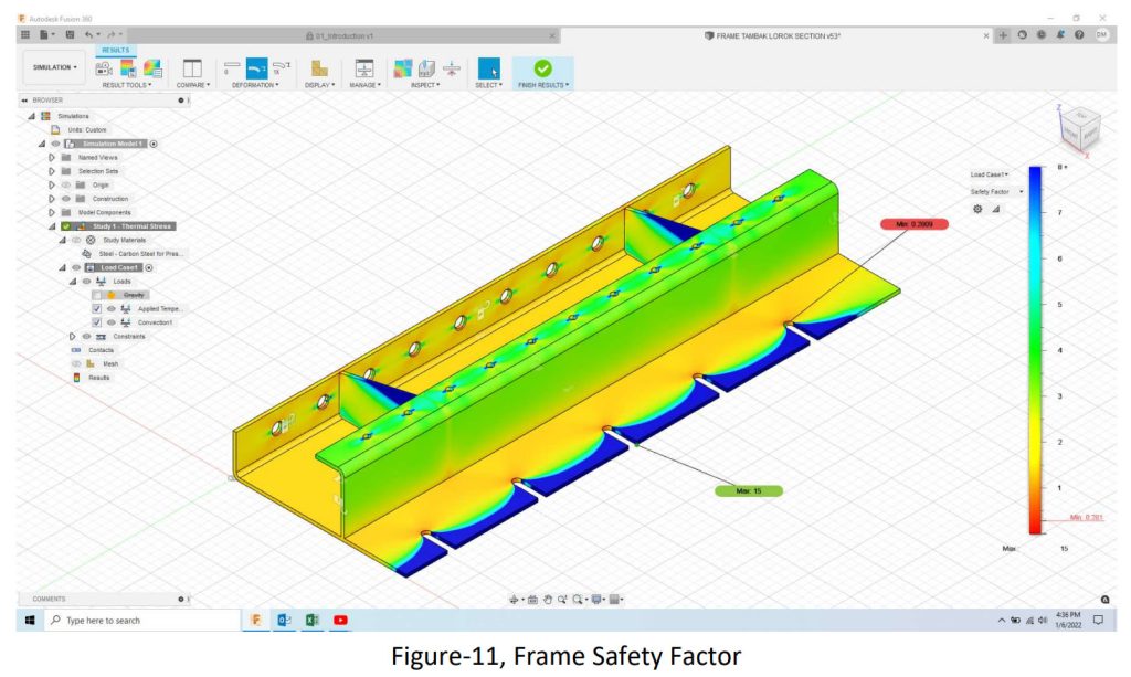
The simulation is carried out with a temp load that is in contact with the insulation 119 °C, the side of the flange that is connected to the ducting flange is fixed on the X, Y and Z axes. In this simulation, it produces thermal stress and safety factor from the frame. The results obtained are Safety Factor < 1.5, and the temperature distribution is as follows:
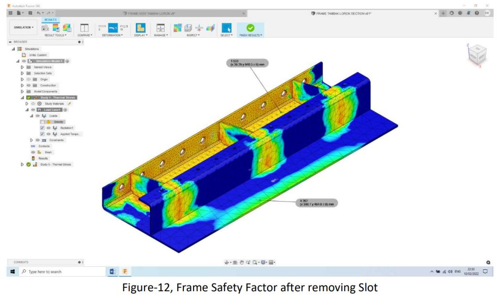
The simulation results show that there are still areas that have a Safety Factor <1.5, therefore the author decided to optimize the design by eliminating slots in the liner area.
The simulation results according to the drawing below:
Based on the simulation results above, the Safety Factor > 1.5 so that geometrically the
construction can be declared safe.
Conclusion
From the results of this simulation, it is concluded that the frame construction is in a safe
condition that works on the HRSG connection with temperatures up to 600 °C, with Ceramic
Blanket and Scallop insulation. Scallop serves to protect the insulation from the influence of
abrasion due to the flow of hot gas in the ducting.
References
[1] Fluid Sealing Association 2010, Technical Handbook Ducting System 4th Edition
[2] Mevada D D, Patel K B., Patel N A., 2012, “A Review on Transient Thermal Analysis for Top Head Nosel of Crack Gas Drier by Finite Element Method”, International Journal of Engineering Research and Application (IJERA), Vol. 2, No.2, 339-345.[3] James Walker Townson 2012, “Problem & Solutions with Expansion joint in Gas Turbine Exhaust System.
[4] ESA (Europan Sealing Association e.V), 2001, “Expansion Joint Engineering Guide”
[5] RAL Deutsches Institut fur Gutesicherung und kennzuichnung e. V, 2010, “Expansion joint
Quality Assurance RAL-GZ 719”
[6] Valery V. Vasiliev, “Composite Pressure Vessels”, Bull Ridge Publishing, 2009.
[7] Timoshenko and Goodier, “Theory of elasticity”, TMH publication, New York, 1951
[8] Ambartsumian, S.A. General Theory of Anisotropic Shells. Nauka Publishers, Moscow (in Russian)-
book.
[9] Kompas.com. “Antisipasi Thermal Stress pada Mesin Turbo”. Diakses pada 24 Sep 2019.
https://otomotif.kompas.com/read/2019/09/24/130100815/antisipasi-thermal-stress-pada-
mobil-mesin-turbo.
[10] Haji-Sheikh A, Beck JV, Agonafer D. Steady-state heat conduction in multilayer bodies.
International Journal of Heat and Mass Transfer 2003; 46: 2363e79.
Newsletter
Enter your email address to join Newsletter Fajar Benua Store

